This allowed the forward centering ring to be repositioned closer to the forward end of the engine tube. The coupler/adapter and the 3/8” threaded rod extension were bonded with JB Weld. The forward centering ring was position in place and the oval eye nuts were tightened to hold everything in place. The forward and aft centering rings were NOT bonded or made permanent yet
The forward and aft centering rings are still removable at this point. Dry wall screws were partially screwed to the forward centering ring along the outer edge to provide a grip to grab onto later. The fin can was slid in and out of the aft airframe to verify general fit, alignment, and to mark various adhesive locations. Everything was checked, and rechecked. Bonding areas were wiped clean with alcohol and the fin can was inserted for the last time. Pro-Set 175-273 adhesive with a tongue depressor was used to apply fillets along the fins and the aft airframe. Everything was allowed to set overnight.
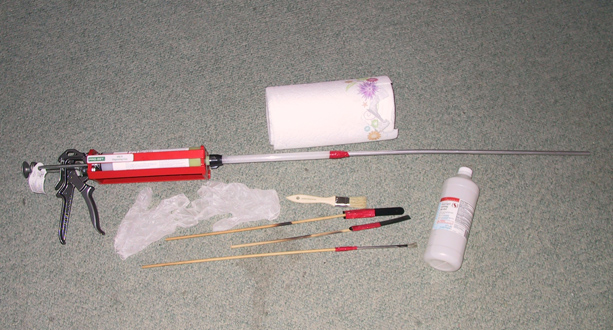
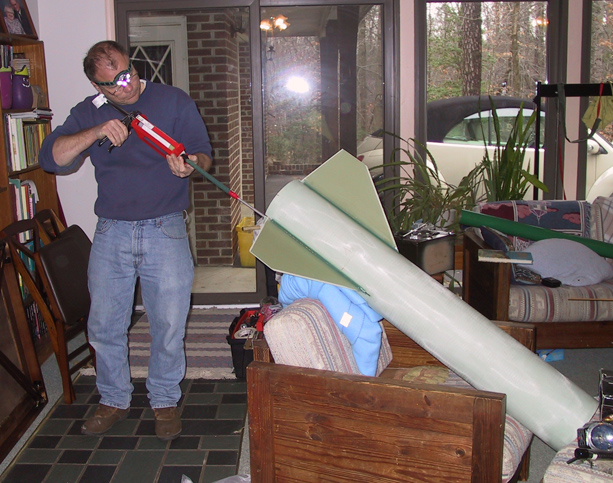
The next morning everything was checked, not that it made a difference as the previous night’s work made it all permanent. A cheap metal tube was cut to length and inserted into the Pro-Set 175-273 mixing wand to extend its reach. Plastic tongue depressors and small brushes were taped to dowels as well. The forward centering ring was removed by grabbing the drywall screws that were previously installed. The Pro-Set 175-273 adhesive with the attached mixing wand extended by the metal tube was then used to force adhesive fillets around the middle centering ring. Alcohol was used to wipe up any drips that might interfere with the reinstallation of the forward centering ring.
The airframe was then flipped and the aft centering ring was removed. Adhesive fillets were forced around the aft side of the middle centering ring and also along the inside of the airframe and fins using the same mixing wand with attached metal tube. The tongue depressor on a stick was used to keep everything neat. Pro-Set 175-273 adhesive is slightly thicker then toothpaste and once applied, it does not go anywhere. This allowed all fillets to be applied at once. Again alcohol was used to clean up any drips that could interfere later.
The fillets were allowed to dry a little. Two inch wide 6 oz fiberglass tape was cut slightly shorter than the fin tang length. A small brush was used to pre-saturate the fiberglass tape with West System epoxy. The fiberglass tape was laminated from the inside of the airframe, over the internal fillet, and back up over the fin tang and engine tube. Cheap dowels and small brushes on a stick help position the fiberglass tape inside the airframe and remove any air bubbles. This process was repeated until all outer internal fin fillets were reinforced with fiberglass tape. Everything was allowed to dry overnight.
The aft rail button location was marked and drilled. Three pieces of 1/8 inch Luan ply was cut as backing. Each piece was separately glued into position on the inside of the aft airframe. The thin layers of Luan ply easily contoured to the inside of the airframe. A blind nut was positioned in place using JB Weld. This allowed the rail button to be removable.
One inch wide 1/8 inch Luan ply strips were then cut and glued in two layers on the inside between the fins, just ½ inch into the aft airframe. The purpose of these strips was to provide additional adhesive surface for the aft centering ring. Well. . ., and to relieve my fears of a “N” motor pushing the entire fin can assembly right through the airframe. A Dremel sanding drum was used to make various adjustments until the aft centering ring was a perfect fit.
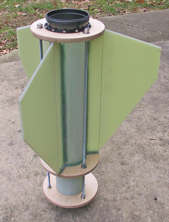
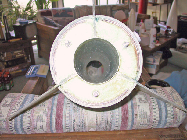
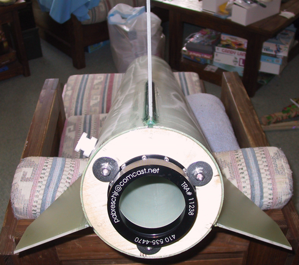
Mega-Foam from Giant Leap was mixed and poured into the internal cavities between the fins. The foam locked everthing in place and provided some additional strength between the fins without adding too much more weight. The Mega-Foam expands up to 20 times its original volume. Despite the careful calculations, the mega-foam slightly overflowed and required cutting and carving to get the aft centering ring to fit again. The aft centering ring was then bonded onto the airframe. A Dremel tool with a grinding wheel was used to nick the fender washers and allow them to fit over the Aeropack Motor Retention system. This tied the fin can assembly together with the aft airframe and motor retention system leaving a single integrated unit.
The forward centering ring was permanently installed. The temporary drywall screws were removed and fillets were made on top using a tongue depressor and Pro-Set 175-273. Fiberglass tape was laminated over the forward bulkhead onto the airframe. The three oval eye nuts were then permanently bolted and bonded in place using JB Weld.
I decided to relax over the holidays and start thinking about the extension and electronics bay for January.


December 2008 Construction Report
Mad Max 8 DD Construction
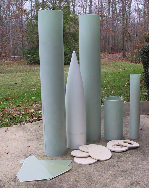
Performance Rocketry's Mad Max8 DD all fiberglass rocket kit
The Performance Rocketry’s Mad Max8 DD kit arrived November 25, 2008 in 3 boxes delivered by the good men from UPS. The first step was to open the boxes and conduct a complete inventory of the components. The Mad Max8 DD kit was quite complete and contained the following:
8” Fiberglass 3:1 Ogive Nosecone
8” G10 Fiberglass Forward Airframe 48 inches
8” G10 Pre-Slotted Aft Airframe 48 inches
G10 Fiberglass coupler/ebay 16 inches
98mm G10 Fiberglass Motor tube 26 inches
(3) G10 Fiberglass 3/16 Thick Beveled fins
(3) ½” Baltic Burch Centering Rings
(1) ½” Baltic Burch Nosecone bulkhead
(2) ½” Baltic Burch outer coupler/ebay bulkheads
(2) ½” Baltic Burch inner coupler/ebay bulkheads
I had to extend the length of the rocket by 16 inches to make the necessary room for the 40 inch long Loki “N” motor that I would eventually fly with. So in addition to the above delivered components, I had to order the following:
G10 Fiberglass coupler 16 inches
8” G10 Fiberglass Airframe 16 inches
This would give the rocket a final length of 12 feet.
Next, all bonding and laminating surfaces were identified and thoroughly roughed up using 60-grit sandpaper. These areas included the fin tang areas, the motor tube, and inside the aft airframe extending forward slightly beyond 34 inches. All centering rings and bulkheads were treated with a coat of West System epoxy, washed, sanded with 80-grit sandpaper, and washed again. This process provides an epoxy barrier that will provide better bonding and laminating strength. All components were then washed to remove all fiberglass, epoxy, and wood dust. The kit was then moved inside.
The pre-slotted fin slots were extended through the bottom of the aft airframe with a hack saw. This allowed a fin can to be constructed that will slide in and out of the main airframe until final assembly. Three 5/16 threaded rods complete with 18 lock washers, washers, and nuts were purchased from the local ACE hardware store. The fin locations were marked on the aft centering ring and 3 5/16 holes were drilled between these fin locations in each centering ring. The threaded rods with the lock washers, washers, and nuts were threaded through the centering rings at the appropriate intervals. One of the fins was used as a spacer between the aft and center centering ring. All measurements were checked, and then check again.
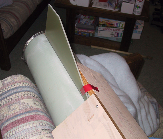
The engine tube assembly, complete with centering rings and threaded rods was inserted back into the aft airframe. Fin locations were marked on the engine tube. Pro-Set 175-273 adhesive was applied to the fin bonding areas on the
engine tube only. Great care was taken to NOT have any adhesives in any other location. A square rig was set up with some duct tape to keep the fin straight and true until dried. A large hose clamp around the aft end was used to remove any risk of distortion. The process was repeated 2 more times until all three fins were bonded to the engine tube.
The fin can assembly was then removed. Pro-Set 175-273 with a mixing wand was used to apply fillets around the fins and engine tube as well as around the middle centering ring. 60-grit sand paper was used to knock any high spots off the fillets. The Aeropack 98mm motor retaining system was then fitted. Three carpenter squares were positioned in the engine tube to insure correct alignment of the Aeropack (I did not have a 98mm motor to use as a guide). Three holes at 11, 3, and 7 oclock were marked and the aft centering ring was removed. The holes were drilled and the threaded inserts were installed. The aft centering ring was then installed on the fin can assembly and the process was repeated for the next 3 holes. Alignment was checked each time. This continued until all 12 holes were completed. The Aeropack 98mm motor retention system was then bolted to the aft centering ring.
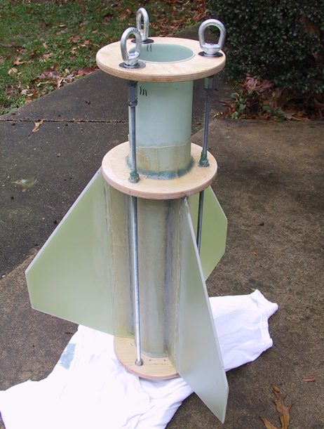
Next, a layer of 6 oz fiberglass tape was laminated over each internal fin fillet, with another layer of 10 oz cloth laminated internally from fin to fin using West System epoxy. Some more 6 oz fiberglass tape was laminated over each side of the middle centering ring and the engine tube. Three threaded rod couplers/adapters (part number 97088A200) and three 3/8” steel oval eye nuts (part number 3019T16) were purchased from McMaster-Carr to extend the threaded rod and take it from 5/16” to 3/8”.
Last Updated:
19 January, 2009 6:35 PM
January 19, 2009 6:35 PM

By Peter E. Abresch Jr.
Fin Fillets using Pro-Set 175-273 Adhesive
First fin drying
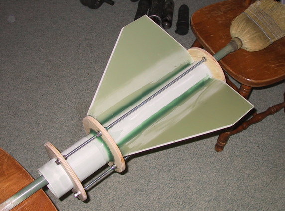
Fin Can awaiting fiberglassing
Completed Fin Can ready for final installation
Tools for working in hard to reach locations
Using the extension to force fillets into the hard to reach areas
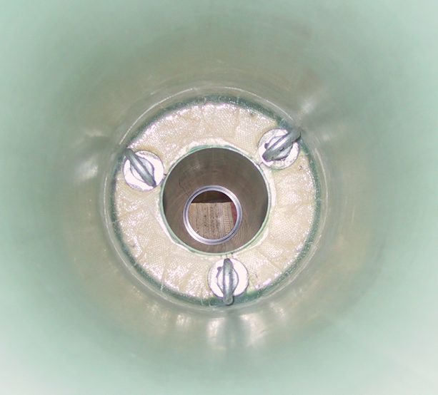
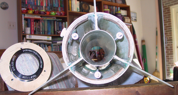
Looking into the interior of the fin can before foaming
Completed fin can installed with Aeropack Motor Retainer
Forward centering ring permanently installed
Fin Can filled with foam