The extension parts were delayed due to UPS losing the shipment. To keep the project moving, the various harnesses and webbing were designed. The plans were provided to Rocket Man to complete the webbing. However, this has also been delayed due to a Kevlar thread shortage caused by the military. Kevlar is being used in vast quantities for the war in Iraq.
The nose cone construction was next. I deviated from the standard nose cone construction and decided to build it with an internal framework that will support adjustable nose weight and also allow access for future installation of various equipment. Under normal circumstances, this rocket should not require additional weight for balance but building it for this possibility now will open future possibilities later.
A 2-inch PVC pipe was cut to 24 inches. All bonding and laminating surfaces were identified and roughed up with coarse grit sandpaper. A wooden plug with a 5/16 inch threaded rod bolted to it was bonded into the forward end of the PVC pipe. The PVC pipe was fitted into the nose as far it could go. The 5/16 threaded rod was adjusted until it protruded into the far tip of the nose cone. Some fender washers and nuts were installed. Holes were drilled through the tip of the nose cone for three ¼ inch threaded rods. One rod was inserted just aft of the forward fender washer. The second rod was inserted on the opposite side and just aft of the second fender washer. The PVC pipe was held in place by these rods as the fender washers prevented the PVC pipe sliding past the ¼ inch rods . Another rod at the tip was inserted to hold the epoxy and structure together.
It was disassembled and epoxy thicken with microfibers was poured into the nose cone. The PVC pipe was installed and the threaded rods inserted into the tip. A centering ring was temporarily installed to keep everything aligned until the epoxy set.
Once the epoxy set, the centering ring with the 5/16 threaded rods attached was permanently bonded into the nose cone with a generous fillet of Pro-Set adhesive. The PVC threaded coupler was also permanently bonded to the PVC pipe. Another centering ring was threaded through the rods and attached over the PVC threaded coupler and bonded in place. This centering ring just fits over the threaded coupler but not over the coupler collar and should reinforce the PVC pipe from shifting aft during acceleration. Fiberglass tape was used to laminate the centering ring to the nosecone. The nosecone was set aside to dry.
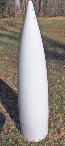
The ¼” threaded rod through the nosecone was grinded down and the entire nosecone was sanded with 220 grit sandpaper and primed with two coats of Dupli-Color filler primer. The nosecone was wet sanded with 400-grit sandpaper, washed, and given two additional coats of primer, a little extra filler primer was provided along the two seams. Another 400-grit wet sanding and washing was all that was necessary.
The 16-inch fiberglass extension and coupler finally arrived. Curtis was also kind enough to cut a special 1” section of the fiberglass airframe to be used for the Ebay collar.
![]()
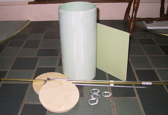
However, the additional centering rings that were ordered are still missing. The newly arrived parts did allow the build to continue. 60-grit sandpaper was once again used to roughen up all bonding surfaces on the fiberglass. The 1” fiberglass collar was bonded around the center of the Ebay coupler. The newly delivered coupler was bonded 8 inches inside the 16-inch airframe extension. After drying, the 16-inch extension was fitted into the aft airframe and three ¼ inch holes were drilled 4 inches down and evenly spaced around the airframe. Laminated Luan with blind nuts were bonded to the inside of the coupler for the ¼ inch pan head bolts used to hold the extension in place.
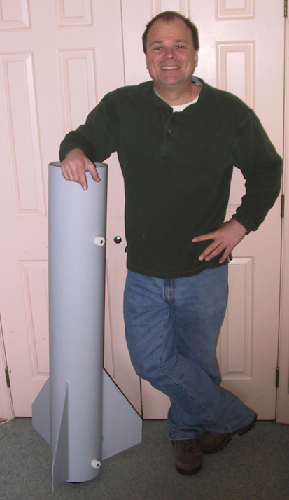
The Ebay coupler was fitted into the forward airframe and two alternating rows of 3 ¼ holes were drilled. Again, laminated Luan with blind nuts were bonded to the inside of the Ebay coupler for support and strength. The 16-inch airframe extension, Ebay collar, and forward airframe were sanded with 220-grit sandpaper, washed, and then primed with 2 coats of Dupli-Color filler primer. The components were then wet sanded with 400-grit sandpaper, washed, and given two additional coats of primer. Another 400-grit wet sanding and washing revealed that all was well.
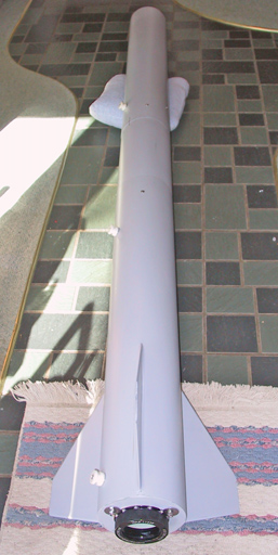
The aft airframe, 16-inch extension, and the forward airframe were test fitted. As luck would have it, one of the Ebay ¼ holes lined up perfectly with the 2 rail buttons on the aft airframe. A third rail button was installed into this hole. Various alignment marks were made for future reference. A 3/16” vent hold was drilled in the forward airframe, 9 inches aft from the top. The aft airframe, 16-inch extension, and the forward airframe were put aside. Final completion of the nose cone is pending arrival of the missing centering rings.
The PerfectFlight HA45K Barometric altimeter arrived. It was mounted to the electronics board. The wiring was started but the work quickly came to a halt. I wanted to make the electronics bay flexible enough where it can be removed easily by simply removing the aft bulkhead and sliding the electronics sled out. In order to do this I would need to include some wiring quick connects/disconnects that would standup to the G forces of rocket flight. A Google search did not reveal what I needed so I requested help from Rocketry Planet. Soon all kinds of options became available and I was back on track.
The end of January saw the arrival of my new interlocking wiring harnesses and the missing centering rings. There is still much left to do.