![]()


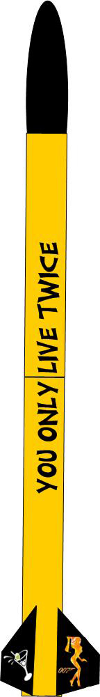
Mirror images were created for the martini and Bond girl for each fin side. Dave from Graphix and Stuff took my files and made vinyl decals at a very reasonable price. The vinyl decals arrived rather quickly and were inspected and set aside.
The newly arrived 98mm centering ring was trimmed to fit inside the nose cone. The 98mm hole was enlarged. Three 5/16” holes were drilled in the centering ring to allow the centering ring to bolt to the 5/16” threaded rods. The nose cone bulkhead was fitted over the top of the centering ring and an additional six ¼” holes were drilled through the bulkhead and the centering ring. Blind nuts were installed into the back of the centering ring. A 3/8” U-bolt was fitted to the center of the bulkhead. A coat of West System epoxy was applied to the centering ring. After drying, the centering ring was bolted and bonded inside the nose cone. Two layers of 6 oz fiberglass tape laminated the centering ring to the nose cone.
Six ¼” bolts’ threads were greased and the bolts were screwed into the centering ring until they slightly protruded past the blind nuts. Multiple layers of painters tape were used around the centering ring hole to create a dam. West System epoxy thickened with microfibers was poured over the centering ring just thick enough to cover the entire centering ring and the three nuts from the 5/16” threaded rod. Once dried, the greased bolts were easily removed. Some minor sanding and grinding ensured a good bulk head fit. A thin strip of foam weather stripping tape was installed over the sanded epoxy to prevent any ejection charge from sneaking into the nose cone. The nose cone bulkhead was bolted onto the nose cone with six machine bolts. The bulk head can be removed and necessary weight adjusted or instruments added if necessary.
The ARTS 2 arrived from Loki Research and was mounted on the electronics sled. Wiring with quick connects was obtained from Bill C at rocketry planet auctions. The wires were cut, stripped, tinned, and soldered. The battery, switch, apogee, and main connections were made and all continuity tested. The ARTS2 was hooked up to the computer and all diagnostics were successfully completed, including firing of the apogee and main electric ematches. The electronics sled was installed into the electronics bay and all bolt holes were sealed with tape except for 1. The Perfectflite HA45k was turned on and a Venturi Vacuum Generator connected to the air compressor was used to suck the air of the ebay through the untaped hole. This simulated altitude and successfully tested the HA45K barometric sensors as when air was allowed back in, the apogee ematch fired followed by the main ematch. The ebay switches were mounted on the ebay collar and 4 equally spaced 3/16 holes were drilled through the ebay collar for air pressure equalization for the barometric sensors. The ebay is completed.
The various rocket components were then weighed to determine parachute requirements. As hard as I tried, I was hoping the rocket to come in below my original predictions of 70 lbs but that is not the case. The current weight to date, excluding recovery harnesses, parachutes, propellant, and final paint job is 61.2 pounds and is divided up as follows: Nose Cone - 9.8 lbs,
Upper Airframe with Ebay attached - 18.0 lbs,
Lower Airframe w/ ext and empty motor including adapter - 33.4 lbs.
Since the nose cone will descend on it own chute, the 70 lbs for the sustainer might still be attainable and I will use this weight for calculating the descent rates. A TAC-9C parachute and a TAC bag were ordered from Giant Leap. The TAC-9C chute should allow the rocket to descend at about 16 feet per second. A 60-inch TAC chute was also ordered for the nose cone to allow it to descend at the same rate.
The use of shear pins was researched while waiting on the recovery parachutes and harnesses to arrive. Shear pins hold the rocket together to prevent premature separation due to deceleration or excessive stress during apogee deployment. Shear pins will shear at a set rate. After completing the research and seeking advice of more experienced rocketeers, it was decided to use three 2-56 shear pins to hold the aft and forward airframes together and six 2-56 shear pins to hold the nose cone. For shear pins, a package of 100 6-6 nylon 2-56 screws (part number 94611A081) were ordered from Mcmaster-Carr. These 2-56 nylon screws have average shear strength of about 35 pounds.
The upper and lower airframes were coupled and aligned. A #51 drill bit was used to drill three equally spaced holes around the aft airframe section and through the ebay coupler. The outer airframe was then threaded using a 2-56 tap. The holes through the ebay coupler were reamed to allow the shear pins to be pushed in and out freely. When the pins shear, they can easily be pushed out of the coupler and unscrewed from the airframe. This process was repeated for the upper airframe and the nose cone to accommodate the six shear pins that will keep the nose cone attached until main deployment. Various calculations will be performed to determine the ejection force to shear these pins during flight.
The recovery harnesses from Rocket Man and the parachutes from Giant Leap arrived. Ground testing, final paint jobs, and final simulations will be started in March. Good March weather will be essential if this candle is to be lit in time for Red Glare VI.